| Picture | Name | LCD Bus | LCD Controller | LCD resolution | Touch Bus | Touch Controller |
|---|---|---|---|---|---|---|
 |
ESP32-C3-LCDkit | SPI | GC9A01 | 240x240 | - | - |
 |
ESP32-S3-BOX | SPI | ILI9342 | 320x240 | I2C | TT21100 |
 |
ESP32-S3-BOX-3 & ESP32-S3-BOX-3B | SPI | ILI9342 | 320x240 | I2C | GT911 |
 |
ESP32-S3-BOX-3(beta) | SPI | ILI9342 | 320x240 | I2C | TT21100 |
 |
ESP32-S3-BOX-Lite | SPI | ST7789 | 320x240 | - | - |
 |
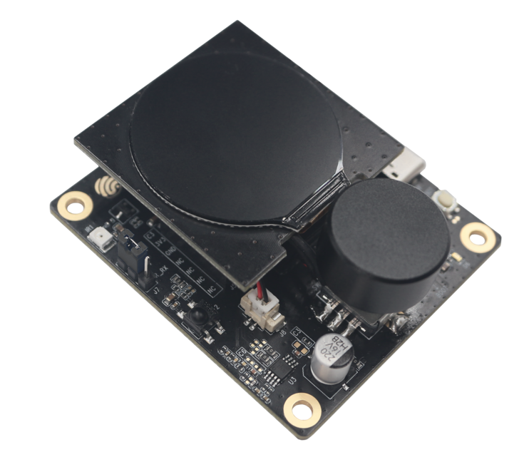
ESP32-S3-EYE | SPI | ST7789 | 240x240 | - | - |
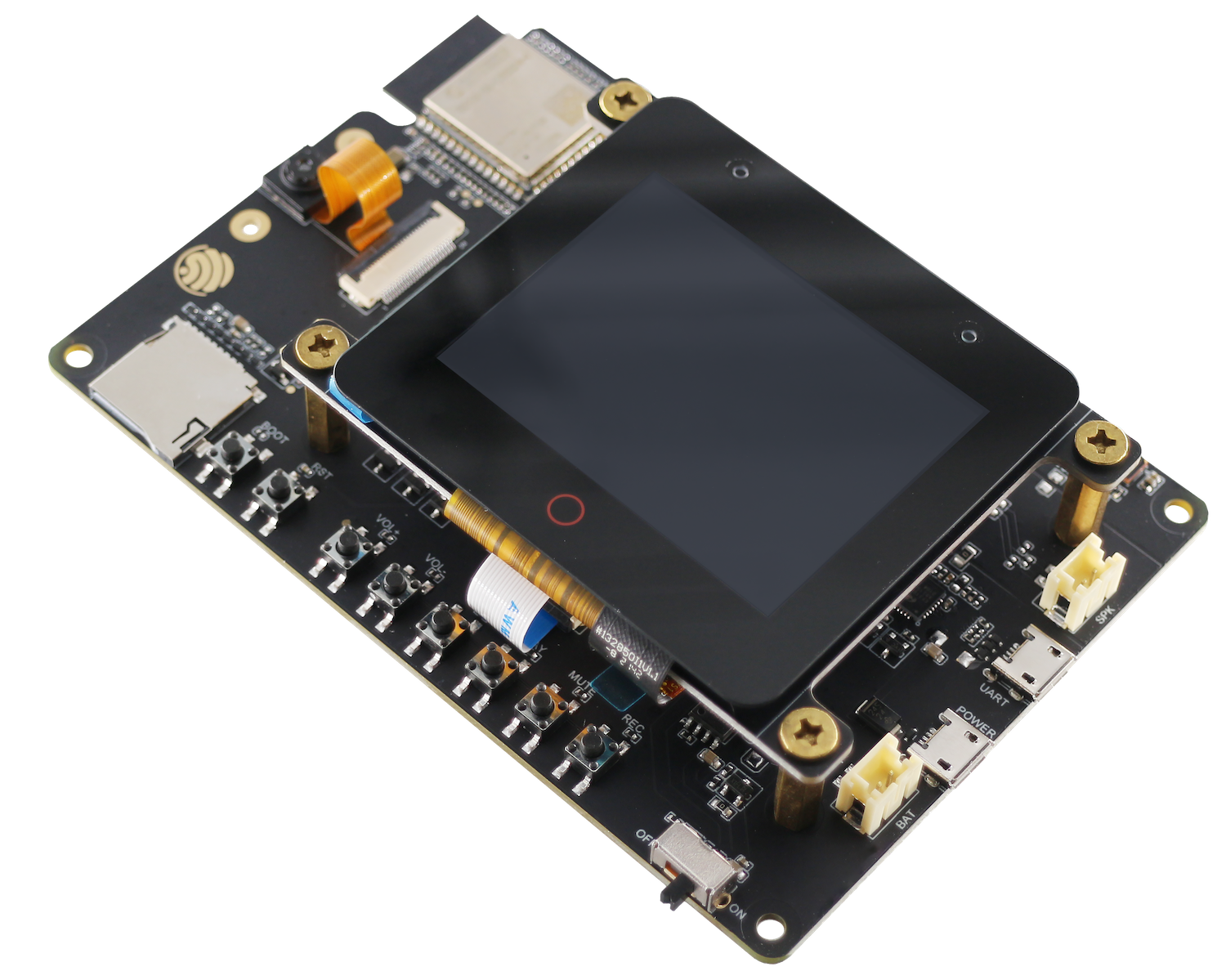 |
ESP32-S3-Korvo-2 | SPI | ILI9342 | 320x240 | I2C | TT21100 |
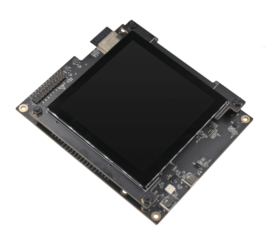 |
ESP32-S3-LCD-EV-Board | 3-wire SPI + RGB | GC9503 | 480x480 | I2C | FT5x06 |
 |
ESP32-S3-LCD-EV-Board-2 | RGB | ST7262E43 | 800x480 | I2C | GT1151 |
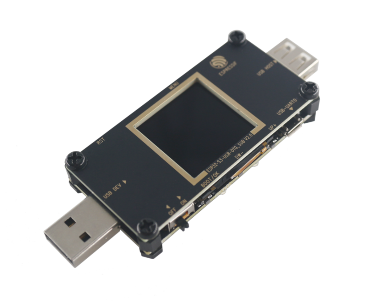 |
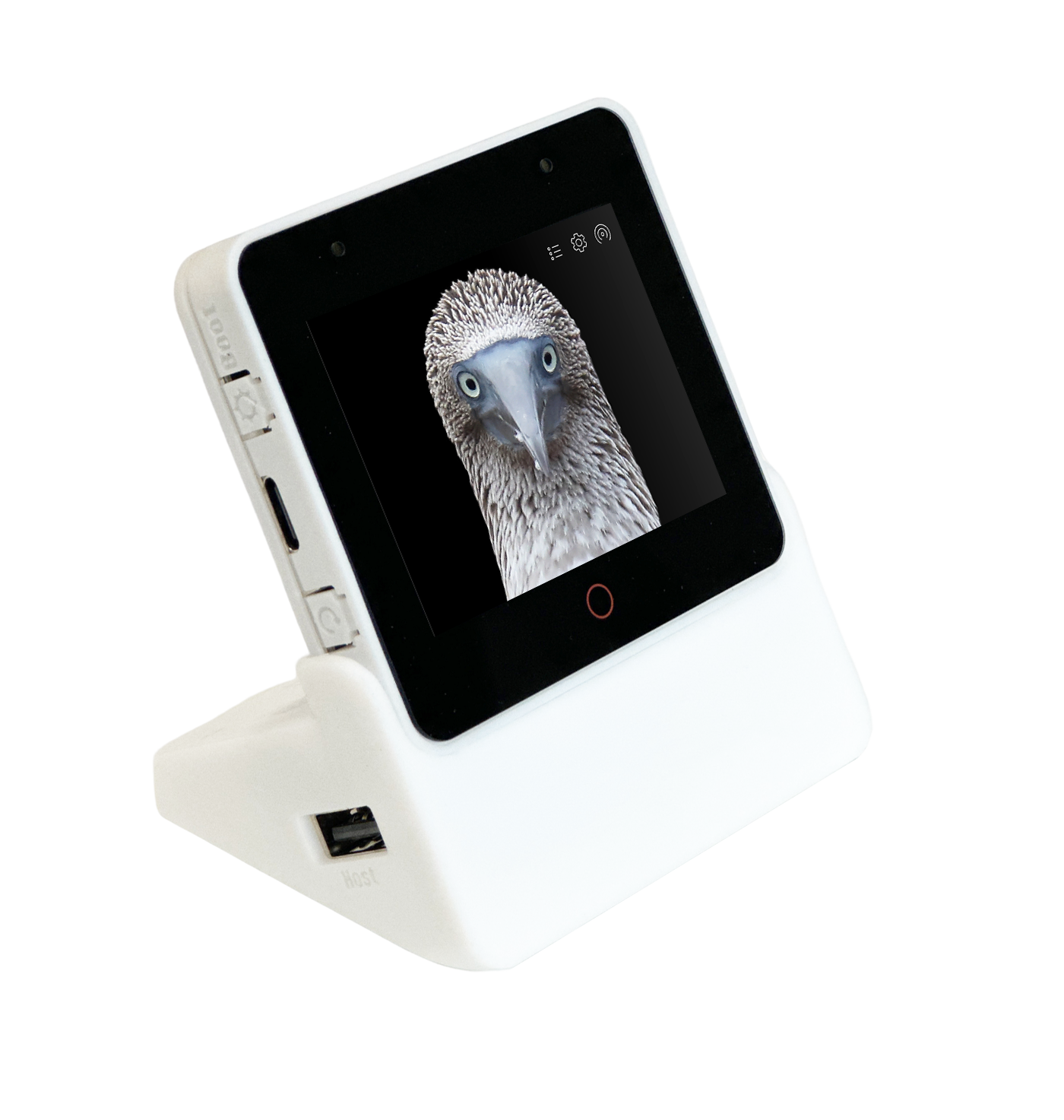
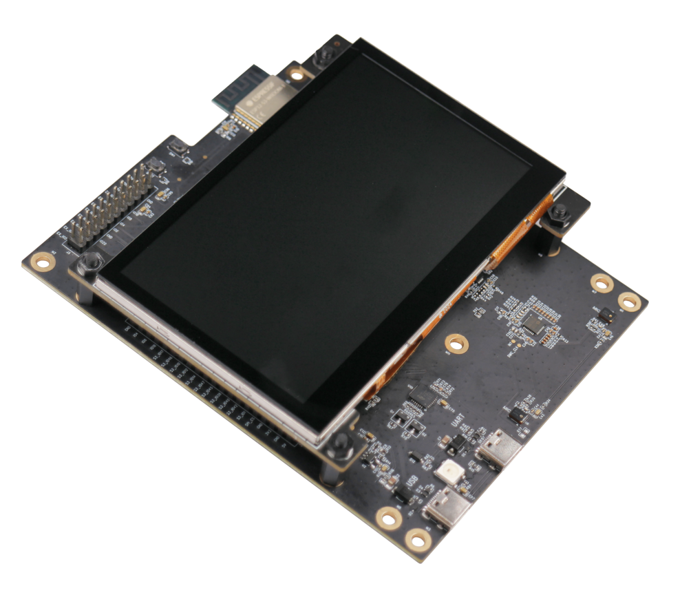
ESP32-S3-USB-OTG | SPI | ST7789 | 240x240 | - | - |
| Picture | Name | LCD Bus | LCD Controller | LCD resolution | Touch Bus | Touch Controller |
|---|---|---|---|---|---|---|
 |
CrowPanel 7.0" | RGB | EK9716BD3 & EK73002ACGB | 800x480 | I2C | GT911 |
| Picture | Name | LCD Bus | LCD Controller | LCD resolution | Touch Bus | Touch Controller |
|---|---|---|---|---|---|---|
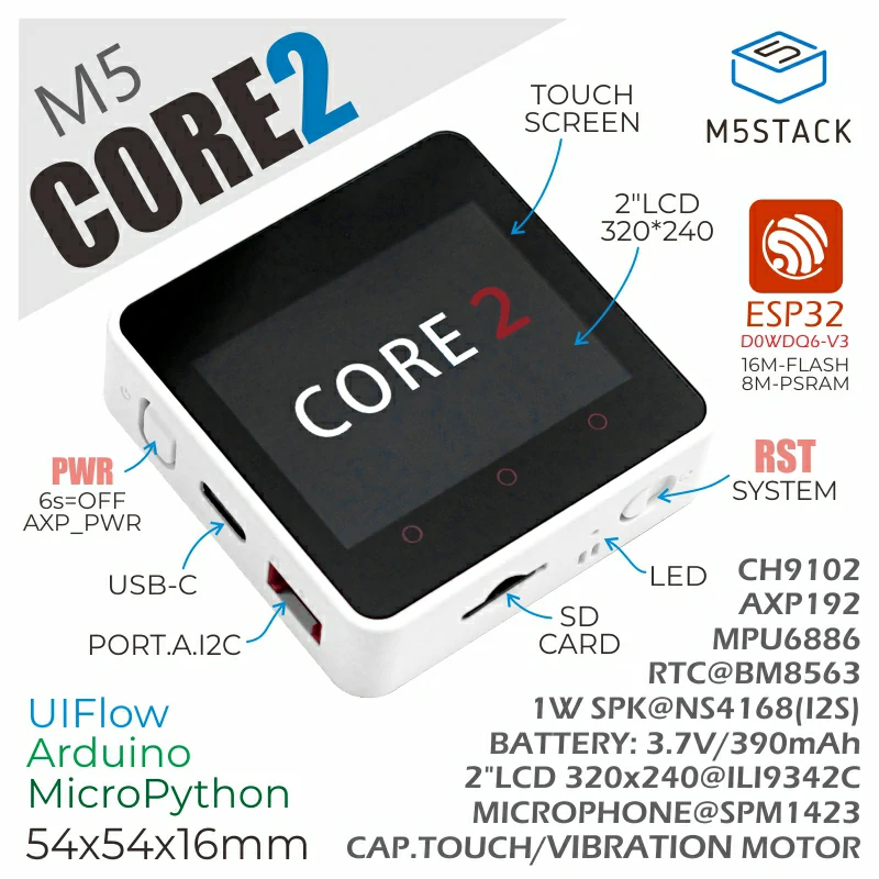 |
M5STACK_M5CORE2 | SPI | ILI9342C | 320x240 | I2C | FT6336U |
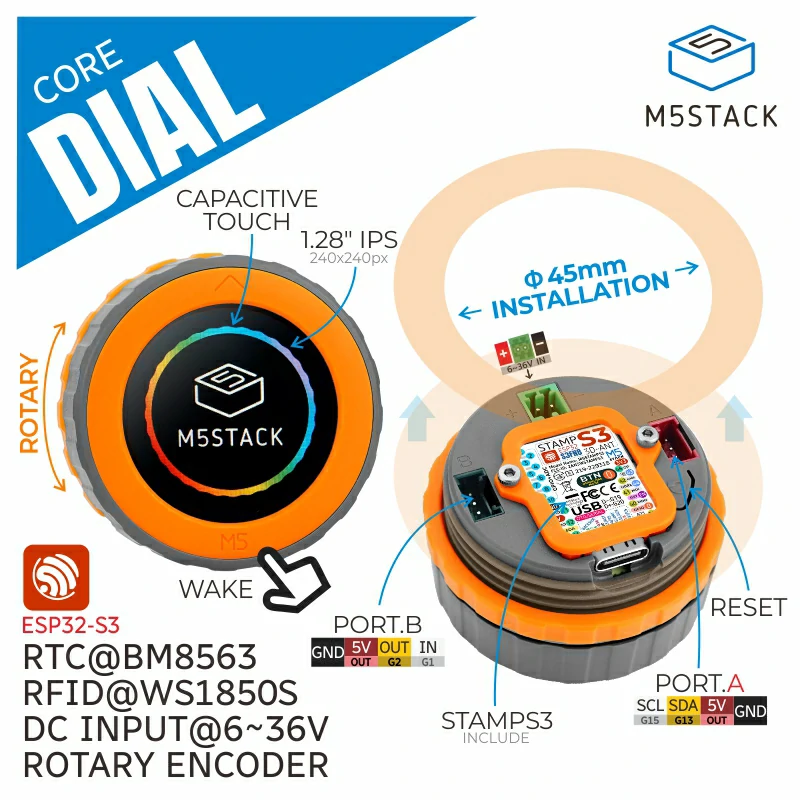 |
M5STACK_M5DIAL | SPI | GC9A01 | 240x240 | I2C | FT5x06 |
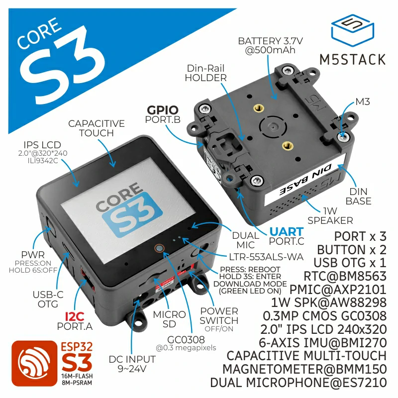 |
M5STACK_M5CORES3 | SPI | ILI9342C | 320x240 | I2C | FT6336U |
| Picture | Name | LCD Bus | LCD Controller | LCD resolution | Touch Bus | Touch Controller |
|---|---|---|---|---|---|---|
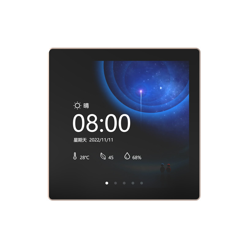 |
ESP32-4848S040C_I_Y_3 | 3-wire SPI + RGB | ST7701 | 480x480 | I2C | GT911 |
| Picture | Name | LCD Bus | LCD Controller | LCD resolution | Touch Bus | Touch Controller |
|---|---|---|---|---|---|---|
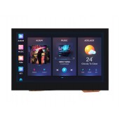 |
ESP32-S3-Touch-LCD-4.3 | RGB | ST7262 | 800x480 | I2C | GT911 |
Below are recommended configurations for developing GUI applications on different development boards. These settings can be adjusted according to specific requirements, and users can navigate to the Tools menu in the Arduino IDE to configure the following settings.
| Supported Boards | Selected Board | PSRAM | Flash Mode | Flash Size | USB CDC On Boot | Partition Scheme |
|---|---|---|---|---|---|---|
| ESP32-C3-LCDkit | ESP32C3 Dev Module | Disabled | QIO | 4MB (32Mb) | Enabled | Default 4MB with spiffs |
| ESP32-S3-BOX | ESP32-S3-BOX | - | - | - | - | 16M Flash (3MB) |
| ESP32-S3-BOX-3 & ESP32-S3-BOX-3B | ESP32S3 Dev Module | OPI | QIO 80MHz | 16MB | Enabled | 16M Flash (3MB) |
| ESP32-S3-BOX-3(beta) | ESP32S3 Dev Module | OPI | QIO 80MHz | 16MB | Enabled | 16M Flash (3MB) |
| ESP32-S3-BOX-Lite | ESP32-S3-BOX | - | - | - | - | 16M Flash (3MB) |
| ESP32-S3-EYE | ESP32S3 Dev Module | OPI | QIO 80MHz | 8MB | Enabled | 8M with spiffs |
| ESP32-S3-Korvo-2 | ESP32S3 Dev Module | OPI | QIO 80MHz | 16MB | Disabled | 16M Flash (3MB) |
| ESP32-S3-LCD-EV-Board | ESP32S3 Dev Module | OPI | QIO 80MHz | 16MB | See Note 1 | 16M Flash (3MB) |
| ESP32-S3-LCD-EV-Board-2 | ESP32S3 Dev Module | OPI | QIO 80MHz | 16MB | See Note 1 | 16M Flash (3MB) |
| ESP32-S3-USB-OTG | ESP32-S3-USB-OTG | - | - | - | - | 8M with spiffs |
| M5STACK-M5CORE2 | M5Stack-Core2 | Enabled | - | - | - | Default |
| M5STACK-M5DIAL | ESP32S3 Dev Module | OPI | QIO 80MHz | 8MB | Disabled | Default |
| M5STACK-M5CORES3 | ESP32S3 Dev Module | OPI | QIO 80MHz | 16MB | Enabled | Default 4MB with spiffs |
| ESP32-4848S040C_I_Y_3 | ESP32S3 Dev Module | OPI | QIO 80MHz | 16MB | Disabled | 16M Flash (3MB) |
| ElecrowCrowPanel 7.0" | ESP32S3 Dev Module | OPI | QIO 80MHz | 4MB | Disabled | Huge App (3MB) |
| Waveshare-ESP32-S3-Touch-LCD-4.3 | ESP32S3 Dev Module | OPI | QIO 80MHz | 8MB | Disabled | 8M with spiffs |
Notes:
-
Enable or disable
USB CDC On Bootbased on the type of port used:- Disable this configuration if using UART port; enable it if using USB port.
- If this configuration differs from previous flashing, first enable
Erase All Flash Before Sketch Upload, then it can be disabled after flashing. - If this configuration does not match the actual port type, it will prevent the development board from printing serial logs correctly.
-
To view more output logs, set
Core Debug LeveltoInfoor a lower level. -
If the predefined partition schemes provided by ESP32 do not meet the requirements, users can also select
Customin the "Partition Scheme" and create a custom partition table fileCustom.csvin thehardware/esp32/3.x.x/tools/partitionsdirectory under the arduino-esp32 installation directory. For detailed information on partition tables, please refer to the ESP-IDF documentation.