Quick reference for the Raspberry Pi Zero W MicroPython
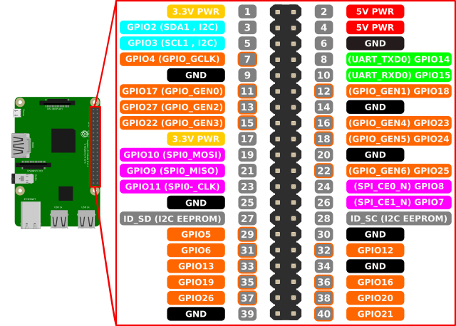
GPIO pin chart from openclipart
The MicroPython REPL is on UART1 (board pin #8=GPIO14=TX, board pin #10=GPIO15=RX) at baudrate 115200, 8 bits, none parity, 1 stop bit.
Use the time module:
import time

time.sleep(1)           # sleep for 1 second
time.sleep_ms(500)      # sleep for 500 milliseconds
time.sleep_us(10)       # sleep for 10 microseconds
start = time.ticks_ms() # get value of millisecond counter
delta = time.ticks_diff(time.ticks_ms(), start) # compute time difference
System timers are supported. Use the machine.Timer class with timer ID of 1 or 3:
from machine import Timer

tim = Timer(1, period=500000, mode=Timer.ONE_SHOT, callback=lambda t:print(1))
tim.init(period=1000000, mode=Timer.PERIODIC, callback=lambda t:print(2))
tim.deinit()
The period is in microseconds.
Timer ID 0 and 2 are used by GPU and not usable.
Use the machine.Pin class:
from machine import Pin

ld = Pin(47, Pin.OUT)   # create output pin on GPIO47 (on-board LED)
ld.value(0)             # set pin to off/low
ld(1)                   # set pin to on/high

p0 = Pin(17, Pin.IN)    # create input pin on GPIO17 (board pin #11)
print(p0.value())       # get value, 0 or 1

p2 = Pin(27, Pin.IN, Pin.PULL_UP) # enable internal pull-up resistor
p3 = Pin(22, Pin.OUT, value=1) # set pin high on creation
Broadcom pin numbering is chosen to control pins not on the on-board connector (the pin connected to on-board LED for example).
The hardware I2C bus only works on following pins: SDA is board pin #3 = GPIO2, SCL is board pin #5 = GPIO3. Software I2C is currently not implemented.
Use the machine.I2C class with bus ID of 1. Bus 0 and bus 2 are not available for users.
from machine import I2C

# construct an I2C bus
i2c = I2C(1)            # only bus #1 is available for application use
i2c.scan()              # returns list of slave addresses

i2c.readfrom(0x3a, 4)   # read 4 bytes from slave device with address 0x3a
i2c.writeto(0x3a, '12') # write '12' to slave device with address 0x3a

buf = bytearray(10)     # create a buffer with 10 bytes
i2c.writeto(0x3a, buf)  # write the given buffer to the slave
The hardware SPI bus only works on following pins: MOSI is board pin #19 = GPIO10, MISO is board pin #21 = GPIO9, SCK is board pin #23 = GPIO11. Software SPI is currently not implemented.
Use the machine.SPI class with bus ID of 0. .
from machine import SPI

# construct an SPI bus
spi = SPI(0)            # only bus #0 is available
spi.init(polarity=1, phase=1, baudrate=10000000)
spi.read(10)            # read 10 bytes on MISO
spi.read(10, write=0xff)      # read 10 bytes while outputing 0xff on MOSI

buf = bytearray(50)     # create a buffer
spi.readinto(buf)       # read into the given buffer (reads 50 bytes in this case)
spi.readinto(buf, write=0xff) # read into the given buffer and output 0xff on MOSI

spi.write(b'12345')     # write 5 bytes on MOSI

buf = bytearray(4)      # create a buffer
spi.write_readinto(b'1234', buf) # write to MOSI and read from MISO into the buffer
spi.write_readinto(buf, buf) # write buf to MOSI and read MISO back into buf
The hardware PWM only works on following pins: GPIO12, GPIO18, GPIO40, GPIO52 for PWM0, GPIO13, GPIO19, GPIO41, GPIO45, GPIO53 for PWM1. You may also use ID of 0 or 1 without specifying output pin if you want to configure alternate functions separately.
The default PWM system clock is configured to be 960KHz and the default PWM period is 960. It means that the default PWM output frequency is 1KHz and you can change its duty cycle in 1/960 step.
from machine import PWM, Pin

p0=PWM(Pin(18))     # use GPIO18 for output. frequency = 1KHz, duty = 50%
p0.init(freq=50)    # 50Hz (1 period = 960000/50 = 19200 ticks)
p0.duty_ticks(480)  # PWM0 duty = 480/19200 = 2.5% = 0.5ms
p0.duty_u16(7864)   # PWM0 duty = 7864/65536 = 12% = 2.4ms
p0.active(False)    # stop PWM0 output
p1=PWM(1)           # use PWM1 with no output pin
SD card is mounted on /sd and can be used in the standard way of accessing files in Python. To disable auto-mounting SD card, set MICROPY_MOUNT_SD_CARD to zero in mpconfigport.mk.
To read/write blocks of the card directly, use machine.SD class:
import os
os.listdir()               # read FAT formatted SD

from machine import SD
sd = SD()
# sd.ioctl(1,0) # This is necessary if SD auto-mount is off
buf=bytearray(512)
sd.readblocks(0x2000, buf) # read the block number 0x2000

# then dump it
for p in range(0, 512, 16):
    print("%04x:" % p, end='')
    for i in range(16):
        print("%02x " % buf[p+i], end='')
    print("  ", end='')
    for i in range(16):
        c = buf[p+i]
        print('.' if c < 32 or c > 127 else chr(c), end='')
    print()
The Raspberry Pi's GPU frame buffer is supported. The image drawn to the frame buffer is immediately displayed on HDMI port.
Use the gpu module with framebuf class:
import gpu, framebuf

gpu.fb_init(640, 480, screen_w=1280, screen_h=720)
fb = framebuf.FrameBuffer(gpu.fb_data(), 640, 480, framebuf.RGB565) # framebuf from GPU
fb.text('MicroPython!', 40, 32, 0xffff)
fb.hline(40, 41, 100, 0xff80)
fb.line(100, 40, 120, 100, 0x7689)
fb.rect(120, 100, 90, 60, 0x3333)
fb.fill_rect(140, 120, 50, 20, 0xfa00)
Some peripherals of Raspberry Pi have its own clock manager. Use the machine.Clock class to configure them. Current supported peripherals are: GP0, GP1, GP2, PCM, PWM. Available clock sources are: OSC(19.2MHz), HDMI(216MHz), PLLD(500MHz), PLLC(1GHz).
from machine import Clock

Clock(Clock.PWM, source=Clock.OSC, divi=20, divf=0, mash=0) # set PWM to OSC/20. (=960KHz)
You can activate the built-in USB host driver by setting MICROPY_HW_USBHOST to non-zero value in mpconfigport.mk. Current implementation is experimental and does not use IRQ ( you cannot interrupt your script by Control-C).
Remember that the current USB keyboard support is VERY unstable. You have to provide against system crash.