Arduino based Oscilloscope with advanced features and two channels. It is a DIY Oscilloscope based on popular Arduino platform.
Arduino-Oscilloscope(here-after reffered to as Osciduino| There is another project with the same name that is why the title name is changed here, after I saw the another project with the same name ie OsciDuino) is an arduino based oscilloscope (tried and tested on arduino uno r3 and mega 2560). Though I would recommend using mega if you can.
it is an educational project to get the insight into the internal workings of a buffered digital oscilloscope (DSO). this version includes advanced functionality to the setup, by including features like dual channel, offset, trigger, time/div, volts/div, and like wise.
The inputs are taken from 2 analog input pins on arduino. the pins however support only voltage range of 0 to +5 volts. so ths oscilloscope works well only if the signal being viewed is +5 volts peak to peak maximum and doesn't have any negative halfs. to view negative halfs, the oscilloscope has to be operated in a +2.5 volts peak mode. this is accomplished externally by scaling the voltage and then offsetting it by +2.5 volts.
An additional display library is included in the master for SPFD5408, if required. Also the schematics for the setup are included in the "arduino files" folder
Currently the code works best with the provided library and thus a specific display driver SPDF5408. This however does not mean that it will not work with other drivers. It's just that behaviour might be different as I have not tested it with any other display. You are welcome to add support for your display driver. if you want to add support to your display. You can either contribute or create a pull-request. An example is adding support for Adafruit 2.5 inch Resistive touch screen display
This is really simple to do just follow the following steps and you are up-and-running.
First and foremost plug in the Display to Arduino. For this see How to assemble the hardware
- Plug in your arduino (uno or mega) to the computer using the usb-2.0
- Open the arduino-oscilloscope-high-freq_v1_5_HW.ino in arduino IDE
- Select your board from "Tools" menu
- Click upload
- You are up and running
/!\ Make sure that 'CH1' and or 'CH2' is set to 'ON'
The following is a "hello world" example for the Osciduino
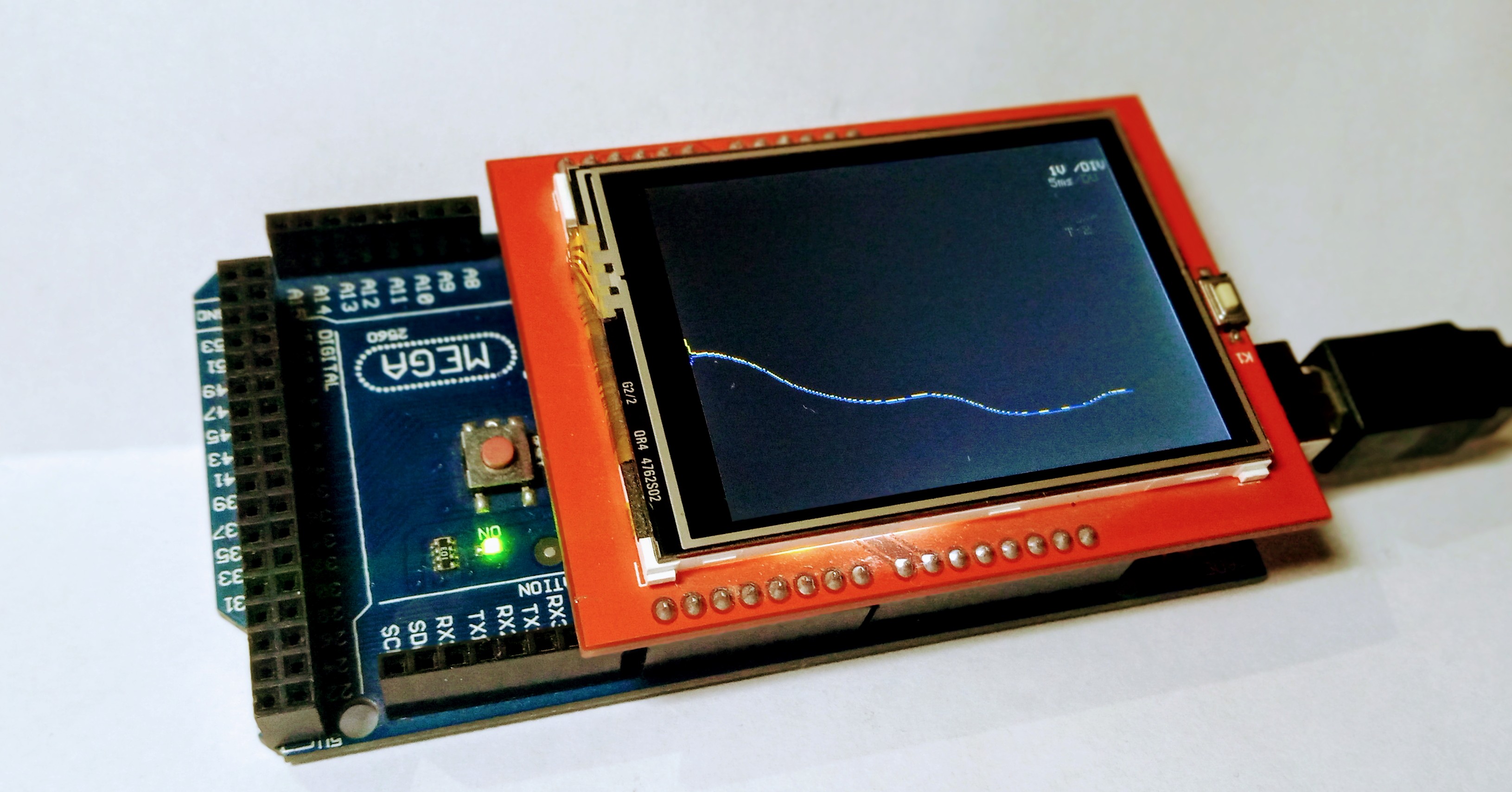
observing charging and Discharging of a capacitor
Power up the Osciduino, as mentioned above in the Quick start. Now on a breadboard connect an electrolytic capacitor in series with a resistor to a square wave generator. Place the probe on the resistor capacitor node. Add a common reference ground between Osciduino and the RC circuit
And you should start seeing the charachteristic rise and fall slopes associated with charging and discharging of the capacitor.
See
-
Examples - Simple RC circuit for more details
-
In Use - ADXL335 for more details

The setup requires an external resistive control interface. Which requires callibration on every boot. As resistance changes easily with temperature and long durations of running. This can be mitigated in a lot of ways, for example by replacing the resistive divider switch configuration by a touch based scheme or a push button scheme encoded into the free GPIO pins on the arduino mega.
Starting version 1.5, the hardware extension support will be addedto the project - release v1.5.0
The code is originally based on the one by Mr. Noriaki Mitsunaga http://n.mtng.org/ele/index.html
- [Osciduino quick setup]
- Osciduino wiki